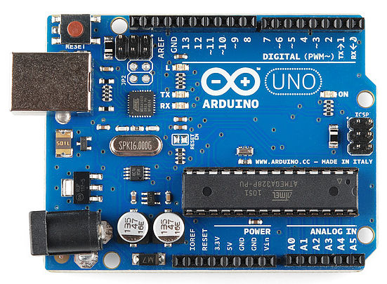
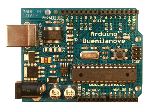
Arduino is composed of two major parts: the Arduino board, which is the piece of hardware you work on when you build your objects; and the Arduino IDE, the piece of software you run on your computer. You use the IDE to create a sketch (a little computer program) that you upload to the Arduino board. The sketch tells the board what to do.
Not too long ago, working on hardware meant building circuits from scratch, using hundreds of different components with strange names like resistor, capacitor, inductor, transistor, and so on. Every circuit was “wired” to do one specific application, and making changes required you to cut wires, solder connections, and more. With the appearance of digital technologies and microprocessors, these functions, which were once implemented with wires, were replaced by software programs. Software is easier to modify than hardware. With a few keypresses, you can radically change the logic of a device and try two or three versions in the same amount of time that it would take you to so er a couple of resistors.
The Arduino Hardware
The Arduino board is a small microcontroller board, which is a small circuit(the board) that contains a whole computer on a small chip (the microcontroller). This computer is at least a thousand times less powerful than the MacBook, but it’s a lot cheaper and very useful to build interesting devices. Look at the Arduino board: you’ll see a black chip with 28 “legs”—that chip is the ATmega328, the heart of your board.
This board contains all the components that are required for this microcontroller to work properly and to communicate with your computer. There are many versions of this board; Among them the Arduino Uno, which is the simplest one to use and the best one for learning on. However, these instructions apply to earlier versions of the board, including the Arduino Duemilanove from 2009.
Here is an explanation of what every element of the board does:
14 Digital IO pins (pins 0–13) : These can be inputs or outputs, which is specified by the sketch you create in the IDE.
6 Analogue In pins (pins 0–5) : These dedicated analogue input pins take analogue values (i.e., voltage readings from a sensor) and convert them into a number between 0 and 1023.
6 Analogue Out pins (pins 3, 5, 6, 9, 10, and 11) : These are actually six of the digital pins that can be reprogrammed for analogue output using the sketch you create in the IDE.
The board can be powered from your computer’s USB port, most USB chargers, or an AC adapter (9 volts recommended, 2.1mm barrel tip, center positive). If there is no power supply plugged into the power socket, the power will come from the USB board, but as soon as you plug a power supply, the board will automatically use it.
For more information : Getting Started with Arduino Part-2


No comments:
Post a Comment