Pages

Wednesday, 22 July 2015

Arduino Digital Basics

Here you will find some of basic examples through which you can learn functions and programming of Digital in Arduino.

1) LED Blinking

2) Arduino + Push Button + LED

3) Debounce (Arduino)

4) Arduino + LED Pattern

5) Arrays in Arduino

6) Play Tone (Melody) on Arduino / Arduino + Piezo buzzer

7) Play tones on multiple speakers using tone() function 

Play tones on multiple speakers using tone() function

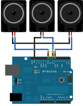
This example shows how to use the tone() command to play different notes on multiple outputs.

The tone() command works by taking over one of the Atmega's internal timers, setting it to the frequency you want, and using the timer to pulse an output pin. Since it's only using one timer, you can only play one note at a time. You can, however, play notes on multiple pins sequentially. To do this, you need to turn the timer off for one pin before moving on to the next.

Hardware Requirements :

* (3) 8-ohm speakers
* (3) 100 ohm resistor
* breadboard
* hook up wire

Circuit :

(This Circuit was made in Fritzing)


Code :

void setup() {

}

void loop() {
  // turn off tone function for pin 8:
  noTone(8);           
  // play a note on pin 6 for 200 ms:
  tone(6, 440, 200);
  delay(200);

  // turn off tone function for pin 6:
  noTone(6);
  // play a note on pin 7 for 500 ms:
  tone(7, 494, 500);
  delay(500);
 
  // turn off tone function for pin 7:
  noTone(7); 
  // play a note on pin 8 for 500 ms:
  tone(8, 523, 300);
  delay(300);
}

Source : www.arduino.cc

Play Tone (Melody) on Arduino / Arduino + Piezo buzzer

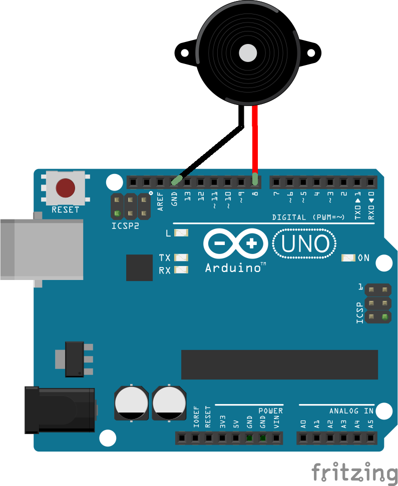
Here, tone() command is used to generate notes.

Hardwares :

Arduino board
a piezo buzzer
hook-up wire

Circuit Diagram :


Code :

// notes in the melody:
int melody[] = {
  NOTE_C4, NOTE_G3,NOTE_G3, NOTE_A3, NOTE_G3,0, NOTE_B3, NOTE_C4};

// note durations: 4 = quarter note, 8 = eighth note, etc.:
int noteDurations[] = {
  4, 8, 8, 4,4,4,4,4 };

void setup() {
  // iterate over the notes of the melody:
  for (int thisNote = 0; thisNote < 8; thisNote++) {

    // to calculate the note duration, take one second
    // divided by the note type.
    //e.g. quarter note = 1000 / 4, eighth note = 1000/8, etc.
    int noteDuration = 1000/noteDurations[thisNote];
    tone(8, melody[thisNote],noteDuration);

    // to distinguish the notes, set a minimum time between them.
    // the note's duration + 30% seems to work well:
    int pauseBetweenNotes = noteDuration * 1.30;
    delay(pauseBetweenNotes);
    // stop the tone playing:
    noTone(8);
  }
}

void loop() {
  // no need to repeat the melody.
}

Arrays in Arduino

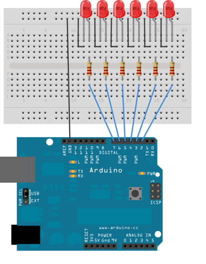
This example shows you how you can turn on a sequence of pins whose numbers are neither contiguous nor necessarily sequential. To do this is, you can put the pin numbers in an array and then use for loops to iterate over the array.

This example makes use of 6 LEDs connected to the pins 2 - 7 on the board using 220 Ohm resistors, just like in the For Loop. However, here the order of the LEDs is determined by their order in the array, not by their physical order.

This technique of putting the pins in an array is very handy. You don't have to have the pins sequential to one another, or even in the same order. You can rearrange them however you want.

Hardware Requirements :

Arduino Board
(6) 220 ohm resistors
(6) LEDs
hook-up wire
breadboard

Circuit :

Code :

int timer = 100;           // The higher the number, the slower the timing.
int ledPins[] = {
  2, 7, 4, 6, 5, 3 };       // an array of pin numbers to which LEDs are attached
int pinCount = 6;           // the number of pins (i.e. the length of the array)

void setup() {
  // the array elements are numbered from 0 to (pinCount - 1).
  // use a for loop to initialize each pin as an output:
  for (int thisPin = 0; thisPin < pinCount; thisPin++)  {
    pinMode(ledPins[thisPin], OUTPUT);     
  }
}

void loop() {
  // loop from the lowest pin to the highest:
  for (int thisPin = 0; thisPin < pinCount; thisPin++) {
    // turn the pin on:
    digitalWrite(ledPins[thisPin], HIGH);  
    delay(timer);                 
    // turn the pin off:
    digitalWrite(ledPins[thisPin], LOW);   

  }

  // loop from the highest pin to the lowest:
  for (int thisPin = pinCount - 1; thisPin >= 0; thisPin--) {
    // turn the pin on:
    digitalWrite(ledPins[thisPin], HIGH);
    delay(timer);
    // turn the pin off:
    digitalWrite(ledPins[thisPin], LOW);
  }
}

Contents Source : www.arduino.cc

Arduino + LED Pattern

This example blinks 6 LEDs attached the Arduino by using a for() loop to cycle back and forth through digital pins 2-7. The LEDS are turned on and off, in sequence, by using both the digitalWrite() and delay() functions .

Hardware Requirements :

* Arduino Board
* (6) 220 ohm resistors
* (6) LEDs
* hook-up wire
* breadboard

Circuit :


Code :

int timer = 100;           // The higher the number, the slower the timing.

void setup() {
  // use a for loop to initialize each pin as an output:
  for (int thisPin = 2; thisPin < 8; thisPin++)  {
    pinMode(thisPin, OUTPUT);     
  }
}

void loop() {
  // loop from the lowest pin to the highest:
  for (int thisPin = 2; thisPin < 8; thisPin++) {
    // turn the pin on:
    digitalWrite(thisPin, HIGH);  
    delay(timer);                 
    // turn the pin off:
    digitalWrite(thisPin, LOW);   
  }

  // loop from the highest pin to the lowest:
  for (int thisPin = 7; thisPin >= 2; thisPin--) {
    // turn the pin on:
    digitalWrite(thisPin, HIGH);
    delay(timer);
    // turn the pin off:
    digitalWrite(thisPin, LOW);
  }
}

(Source : www.arduino.cc)

Debounce (Arduino)

What is Debounce?

Debounce means checking twice in a short period of time to make sure it's definitely pressed. Without debouncing, pressing the button once can appear to the code as multiple presses. Makes use of the millis() function to keep track of the time when the button is pressed.

Hardware Requirements :

* Arduino Board
* momentary button or switch
* 10K ohm resistor
* breadboard
* hook-up wire

Circuit :

(Image Source: www.arduino.cc)

Code :

// set pin numbers:
const int buttonPin = 2;    // the number of the pushbutton pin
const int ledPin = 13;      // the number of the LED pin

// Variables will change:
int ledState = HIGH;         // the current state of the output pin
int buttonState;             // the current reading from the input pin
int lastButtonState = LOW;   // the previous reading from the input pin

// the following variables are long's because the time, measured in miliseconds,
// will quickly become a bigger number than can be stored in an int.
long lastDebounceTime = 0;  // the last time the output pin was toggled
long debounceDelay = 50;    // the debounce time; increase if the output flickers

void setup() {
  pinMode(buttonPin, INPUT);
  pinMode(ledPin, OUTPUT);

  // set initial LED state
  digitalWrite(ledPin, ledState);
}

void loop() {
  // read the state of the switch into a local variable:
  int reading = digitalRead(buttonPin);

  // check to see if you just pressed the button
  // (i.e. the input went from LOW to HIGH),  and you've waited
  // long enough since the last press to ignore any noise: 

  // If the switch changed, due to noise or pressing:
  if (reading != lastButtonState) {
    // reset the debouncing timer
    lastDebounceTime = millis();
  }
 
  if ((millis() - lastDebounceTime) > debounceDelay) {
    // whatever the reading is at, it's been there for longer
    // than the debounce delay, so take it as the actual current state:

    // if the button state has changed:
    if (reading != buttonState) {
      buttonState = reading;

      // only toggle the LED if the new button state is HIGH
      if (buttonState == HIGH) {
        ledState = !ledState;
      }
    }
  }
 
  // set the LED:
  digitalWrite(ledPin, ledState);

  // save the reading.  Next time through the loop,
  // it'll be the lastButtonState:
  lastButtonState = reading;
}
Arduino + Push Button + LED

In this example, LED will turn on by pressing Switch/Pushbutton.

Hardware Requirements :

* Arduino Board
* Switch / Push Button
* 10K ohm resistor
* breadboard
* hook-up wire

Circuit :
(You can Draw such circuits in Fritzing)


Code :

// set pin numbers:
const int buttonPin = 2;     // the number of the pushbutton pin
const int ledPin =  13;      // the number of the LED pin

// variables will change:
int buttonState = 0;         // variable for reading the pushbutton status

void setup() {
  // initialize the LED pin as an output:
  pinMode(ledPin, OUTPUT);     
  // initialize the pushbutton pin as an input:
  pinMode(buttonPin, INPUT);    
}

void loop(){
  // read the state of the pushbutton value:
  buttonState = digitalRead(buttonPin);

  // check if the pushbutton is pressed.
  // if it is, the buttonState is HIGH:
  if (buttonState == HIGH) {    
    // turn LED on:   
    digitalWrite(ledPin, HIGH); 
  }
  else {
    // turn LED off:
    digitalWrite(ledPin, LOW);
  }
}

Source : www.arduino.cc

Wednesday, 1 July 2015

Your first sketch with Arduino/LED Blinking

LEDs are available in a range of colors, but the LED connected to pin 13 on the Arduino is normally green. The LED lights up when a current is applied to it, so you can use pin 13 like a switch. When you switch it on, it will light up the LED, and when you switch it off, it will turn off the LED.
Let’s start by writing the sketch.

Start up the Arduino IDE and copy the following code. It might look a little overwhelming at first, but don’t worry. We’ll go into more detail about what this all means later in the upcoming tutorials.

void setup(){
pinMode(13, OUTPUT);
}
void loop(){
digitalWrite(13, HIGH);
delay(1000);
digitalWrite(13, LOW);
delay(1000);
}

The code is straightforward. You’re assigning digital pin 13 as an output, and then you’re looping through some code that switches pin 13 on to HIGH or LOW for 1 second. The delay value is given in milliseconds, so 1000 milliseconds give you a delay time of 1 second.

Now connect LED with Arduino board as shown in fig :

+LED -> Arduino Pin -13
-LED -> Ground

Uploading:
Go to Tools>Board> Select Board which you have

Now,

Go to Tools>Serial Port>Select Port on which Arduino is connected with your Computer.

Now click on upload button as shown in fig:

or
Press ctrl+U

LED will start blinking at 1 sec interval if you follow all the instruction in right order.