Pages

Wednesday, 22 July 2015

Arduino Digital Basics

Here you will find some of basic examples through which you can learn functions and programming of Digital in Arduino.

1) LED Blinking

2) Arduino + Push Button + LED

3) Debounce (Arduino)

4) Arduino + LED Pattern

5) Arrays in Arduino

6) Play Tone (Melody) on Arduino / Arduino + Piezo buzzer

7) Play tones on multiple speakers using tone() function 

Play tones on multiple speakers using tone() function

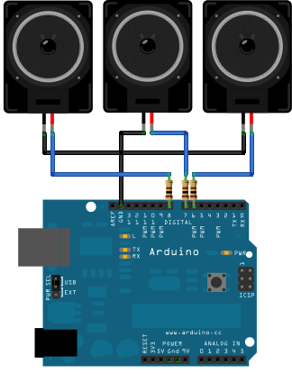
This example shows how to use the tone() command to play different notes on multiple outputs.

The tone() command works by taking over one of the Atmega's internal timers, setting it to the frequency you want, and using the timer to pulse an output pin. Since it's only using one timer, you can only play one note at a time. You can, however, play notes on multiple pins sequentially. To do this, you need to turn the timer off for one pin before moving on to the next.

Hardware Requirements :

* (3) 8-ohm speakers
* (3) 100 ohm resistor
* breadboard
* hook up wire

Circuit :

(This Circuit was made in Fritzing)


Code :

void setup() {

}

void loop() {
  // turn off tone function for pin 8:
  noTone(8);           
  // play a note on pin 6 for 200 ms:
  tone(6, 440, 200);
  delay(200);

  // turn off tone function for pin 6:
  noTone(6);
  // play a note on pin 7 for 500 ms:
  tone(7, 494, 500);
  delay(500);
 
  // turn off tone function for pin 7:
  noTone(7); 
  // play a note on pin 8 for 500 ms:
  tone(8, 523, 300);
  delay(300);
}

Source : www.arduino.cc

Play Tone (Melody) on Arduino / Arduino + Piezo buzzer

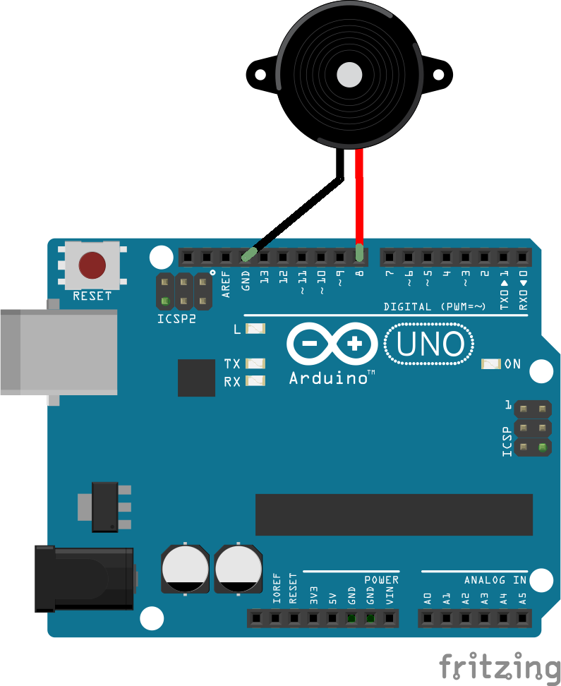
Here, tone() command is used to generate notes.

Hardwares :

Arduino board
a piezo buzzer
hook-up wire

Circuit Diagram :


Code :

// notes in the melody:
int melody[] = {
  NOTE_C4, NOTE_G3,NOTE_G3, NOTE_A3, NOTE_G3,0, NOTE_B3, NOTE_C4};

// note durations: 4 = quarter note, 8 = eighth note, etc.:
int noteDurations[] = {
  4, 8, 8, 4,4,4,4,4 };

void setup() {
  // iterate over the notes of the melody:
  for (int thisNote = 0; thisNote < 8; thisNote++) {

    // to calculate the note duration, take one second
    // divided by the note type.
    //e.g. quarter note = 1000 / 4, eighth note = 1000/8, etc.
    int noteDuration = 1000/noteDurations[thisNote];
    tone(8, melody[thisNote],noteDuration);

    // to distinguish the notes, set a minimum time between them.
    // the note's duration + 30% seems to work well:
    int pauseBetweenNotes = noteDuration * 1.30;
    delay(pauseBetweenNotes);
    // stop the tone playing:
    noTone(8);
  }
}

void loop() {
  // no need to repeat the melody.
}

Arrays in Arduino

This example shows you how you can turn on a sequence of pins whose numbers are neither contiguous nor necessarily sequential. To do this is, you can put the pin numbers in an array and then use for loops to iterate over the array.

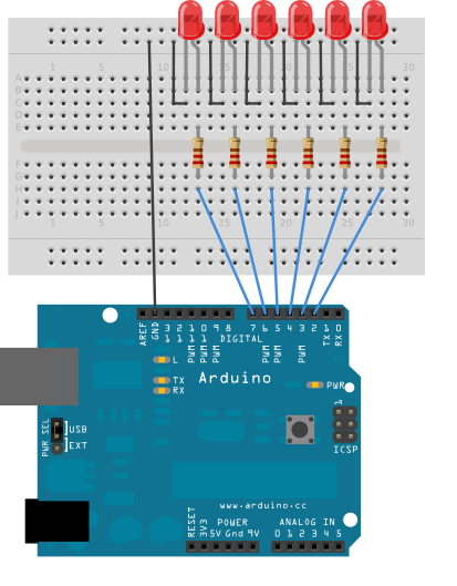
This example makes use of 6 LEDs connected to the pins 2 - 7 on the board using 220 Ohm resistors, just like in the For Loop. However, here the order of the LEDs is determined by their order in the array, not by their physical order.

This technique of putting the pins in an array is very handy. You don't have to have the pins sequential to one another, or even in the same order. You can rearrange them however you want.

Hardware Requirements :

Arduino Board
(6) 220 ohm resistors
(6) LEDs
hook-up wire
breadboard

Circuit :

Code :

int timer = 100;           // The higher the number, the slower the timing.
int ledPins[] = {
  2, 7, 4, 6, 5, 3 };       // an array of pin numbers to which LEDs are attached
int pinCount = 6;           // the number of pins (i.e. the length of the array)

void setup() {
  // the array elements are numbered from 0 to (pinCount - 1).
  // use a for loop to initialize each pin as an output:
  for (int thisPin = 0; thisPin < pinCount; thisPin++)  {
    pinMode(ledPins[thisPin], OUTPUT);     
  }
}

void loop() {
  // loop from the lowest pin to the highest:
  for (int thisPin = 0; thisPin < pinCount; thisPin++) {
    // turn the pin on:
    digitalWrite(ledPins[thisPin], HIGH);  
    delay(timer);                 
    // turn the pin off:
    digitalWrite(ledPins[thisPin], LOW);   

  }

  // loop from the highest pin to the lowest:
  for (int thisPin = pinCount - 1; thisPin >= 0; thisPin--) {
    // turn the pin on:
    digitalWrite(ledPins[thisPin], HIGH);
    delay(timer);
    // turn the pin off:
    digitalWrite(ledPins[thisPin], LOW);
  }
}

Contents Source : www.arduino.cc

Arduino + LED Pattern

This example blinks 6 LEDs attached the Arduino by using a for() loop to cycle back and forth through digital pins 2-7. The LEDS are turned on and off, in sequence, by using both the digitalWrite() and delay() functions .

Hardware Requirements :

* Arduino Board
* (6) 220 ohm resistors
* (6) LEDs
* hook-up wire
* breadboard

Circuit :


Code :

int timer = 100;           // The higher the number, the slower the timing.

void setup() {
  // use a for loop to initialize each pin as an output:
  for (int thisPin = 2; thisPin < 8; thisPin++)  {
    pinMode(thisPin, OUTPUT);     
  }
}

void loop() {
  // loop from the lowest pin to the highest:
  for (int thisPin = 2; thisPin < 8; thisPin++) {
    // turn the pin on:
    digitalWrite(thisPin, HIGH);  
    delay(timer);                 
    // turn the pin off:
    digitalWrite(thisPin, LOW);   
  }

  // loop from the highest pin to the lowest:
  for (int thisPin = 7; thisPin >= 2; thisPin--) {
    // turn the pin on:
    digitalWrite(thisPin, HIGH);
    delay(timer);
    // turn the pin off:
    digitalWrite(thisPin, LOW);
  }
}

(Source : www.arduino.cc)

Debounce (Arduino)

What is Debounce?

Debounce means checking twice in a short period of time to make sure it's definitely pressed. Without debouncing, pressing the button once can appear to the code as multiple presses. Makes use of the millis() function to keep track of the time when the button is pressed.

Hardware Requirements :

* Arduino Board
* momentary button or switch
* 10K ohm resistor
* breadboard
* hook-up wire

Circuit :

(Image Source: www.arduino.cc)

Code :

// set pin numbers:
const int buttonPin = 2;    // the number of the pushbutton pin
const int ledPin = 13;      // the number of the LED pin

// Variables will change:
int ledState = HIGH;         // the current state of the output pin
int buttonState;             // the current reading from the input pin
int lastButtonState = LOW;   // the previous reading from the input pin

// the following variables are long's because the time, measured in miliseconds,
// will quickly become a bigger number than can be stored in an int.
long lastDebounceTime = 0;  // the last time the output pin was toggled
long debounceDelay = 50;    // the debounce time; increase if the output flickers

void setup() {
  pinMode(buttonPin, INPUT);
  pinMode(ledPin, OUTPUT);

  // set initial LED state
  digitalWrite(ledPin, ledState);
}

void loop() {
  // read the state of the switch into a local variable:
  int reading = digitalRead(buttonPin);

  // check to see if you just pressed the button
  // (i.e. the input went from LOW to HIGH),  and you've waited
  // long enough since the last press to ignore any noise: 

  // If the switch changed, due to noise or pressing:
  if (reading != lastButtonState) {
    // reset the debouncing timer
    lastDebounceTime = millis();
  }
 
  if ((millis() - lastDebounceTime) > debounceDelay) {
    // whatever the reading is at, it's been there for longer
    // than the debounce delay, so take it as the actual current state:

    // if the button state has changed:
    if (reading != buttonState) {
      buttonState = reading;

      // only toggle the LED if the new button state is HIGH
      if (buttonState == HIGH) {
        ledState = !ledState;
      }
    }
  }
 
  // set the LED:
  digitalWrite(ledPin, ledState);

  // save the reading.  Next time through the loop,
  // it'll be the lastButtonState:
  lastButtonState = reading;
}
Arduino + Push Button + LED

In this example, LED will turn on by pressing Switch/Pushbutton.

Hardware Requirements :

* Arduino Board
* Switch / Push Button
* 10K ohm resistor
* breadboard
* hook-up wire

Circuit :
(You can Draw such circuits in Fritzing)


Code :

// set pin numbers:
const int buttonPin = 2;     // the number of the pushbutton pin
const int ledPin =  13;      // the number of the LED pin

// variables will change:
int buttonState = 0;         // variable for reading the pushbutton status

void setup() {
  // initialize the LED pin as an output:
  pinMode(ledPin, OUTPUT);     
  // initialize the pushbutton pin as an input:
  pinMode(buttonPin, INPUT);    
}

void loop(){
  // read the state of the pushbutton value:
  buttonState = digitalRead(buttonPin);

  // check if the pushbutton is pressed.
  // if it is, the buttonState is HIGH:
  if (buttonState == HIGH) {    
    // turn LED on:   
    digitalWrite(ledPin, HIGH); 
  }
  else {
    // turn LED off:
    digitalWrite(ledPin, LOW);
  }
}

Source : www.arduino.cc

Wednesday, 1 July 2015

Your first sketch with Arduino/LED Blinking

LEDs are available in a range of colors, but the LED connected to pin 13 on the Arduino is normally green. The LED lights up when a current is applied to it, so you can use pin 13 like a switch. When you switch it on, it will light up the LED, and when you switch it off, it will turn off the LED.
Let’s start by writing the sketch.

Start up the Arduino IDE and copy the following code. It might look a little overwhelming at first, but don’t worry. We’ll go into more detail about what this all means later in the upcoming tutorials.

void setup(){
pinMode(13, OUTPUT);
}
void loop(){
digitalWrite(13, HIGH);
delay(1000);
digitalWrite(13, LOW);
delay(1000);
}

The code is straightforward. You’re assigning digital pin 13 as an output, and then you’re looping through some code that switches pin 13 on to HIGH or LOW for 1 second. The delay value is given in milliseconds, so 1000 milliseconds give you a delay time of 1 second.

Now connect LED with Arduino board as shown in fig :

+LED -> Arduino Pin -13
-LED -> Ground

Uploading:
Go to Tools>Board> Select Board which you have

Now,

Go to Tools>Serial Port>Select Port on which Arduino is connected with your Computer.

Now click on upload button as shown in fig:

or
Press ctrl+U

LED will start blinking at 1 sec interval if you follow all the instruction in right order.

Friday, 20 February 2015

Getting Started with Arduino Part-2


The Software (IDE)


The IDE (Integrated Development Environment) is a special program running on your computer that allows you to write sketches for the Arduino board in a simple language modeled after the Processing (www.processing.org) language. The magic happens when you press the button that uploads the sketch to the board: the code that you have written is translated into the C language (which is generally quite hard for a beginner to use), and is passed to the avr-gcc compiler, an important piece of open source software that makes the final translation into the language understood by the microcontroller. This last step is quite important, because it’s where Arduino makes your life simple by hiding away as much as possible of the complexities of programming microcontrollers. The programming cycle on Arduino is basically as follows:

» Plug your board into a USB port on your computer.
» Write a sketch that will bring the board to life.
» Upload this sketch to the board through the USB connection and wait
a couple of seconds for the board to restart.
» The board executes the sketch that you wrote.


Installing Arduino on Your Computer


To program the Arduino board, you must first download the development environment (the IDE) from here: www.arduino.cc/en/Main/Software. Choose the right version for your operating system.


Download the file and double-click on it to open it; on Windows or Linux, this creates a folder named arduino- version], such as arduino-1.0. Drag the folder to wherever you want it: your desktop, your Program Files folder (on Windows), etc. On the Mac, double-clicking it will open a disk image with an Arduino application (drag it to your Applications folder). Now whenever you want to run the Arduino IDE, you’ll open up the arduino (Windows and Linux) or Applications folder (Mac), and double-click the Arduino icon. Don’t do this yet, though; there is one more step. 


Now you must install the drivers that allow your computer to talk to your board through the USB port.


Installing Drivers: Macintosh

  • The Arduino Uno on a Mac uses the drivers provided by the operating system, so the procedure is quite simple. Plug the board into your computer.

  • The PWR light on the board should come on and the yellow LED labeled “L” should start blinking.

  • You might see a popup window telling you that a new network interface has been detected.

  • If that happens, Click “Network Preferences...”, and when it opens, click “Apply”. The Uno will show up as “Not Configured”, but it’s working properly. Quit System Preferences.


Installing Drivers: Windows


  • Plug the Arduino board into the computer; when the Found New Hardware Wizard window comes up, Windows will first try to find the driver on the Windows Update site.

  • Windows XP will ask you whether to check Windows Update; if you don’t want to use Windows Update, select the “No, not at this time” option and click Next.
  • On the next screen, choose “Install from a list or specific location” and click Next.
  • Navigate to and select the Uno’s driver file, named ArduinoUNO.inf, located in the “Drivers” folder of the Arduino Software download (not the “FTDI USB Drivers” sub-directory). Windows will finish up the driver installation from there.
  •  If you have an older board, look for instructions here: www.arduino.cc/en/Guide/Windows.


Once the drivers are installed, you can launch the Arduino IDE and start using Arduino. Next, you must figure out which serial port is assigned to your Arduino board—you’ll need that information to program it later.

Port Identification: Macintosh 
From the Tools menu in the Arduino IDE, select “Serial Port” and select the port that begins with /dev/cu.usbmodem; this is the name that your computer uses to refer to the Arduino board

Port Identification: Windows
On Windows, the process is a bit more complicated—at least at the beginning. Open the Device Manager by clicking the Start menu, right-clicking on Computer (Vista) or My Computer (XP), and choosing Properties. On Windows XP, click Hardware and choose Device Manager. On Vista, click
Device Manager (it appears in the list of tasks on the left of the window). Look for the Arduino device in the list under “Ports (COM & LPT)”. The Arduino will appear as “Arduino UNO” and will have a name like COM3.


Once you’ve figured out the COM port assignment, you can select that port from the Tools > Serial Port menu in the Arduino IDE. Now the Arduino development environment can talk to the Arduino board and program it.

Wednesday, 18 February 2015

Getting Started with Arduino Part-1

Arduino is composed of two major parts: the Arduino board, which is the piece of hardware you work on when you build your objects; and the Arduino IDE, the piece of software you run on your computer. You use the IDE to create a sketch (a little computer program) that you upload to the Arduino board. The sketch tells the board what to do.

Not too long ago, working on hardware meant building circuits from scratch, using hundreds of different components with strange names like resistor, capacitor, inductor, transistor, and so on. Every circuit was “wired” to do one specific application, and making changes required you to cut wires, solder connections, and more. With the appearance of digital technologies and microprocessors, these functions, which were once implemented with wires, were replaced by software programs. Software is easier to modify than hardware. With a few keypresses, you can radically change the logic of a device and try two or three versions in the same amount of time that it would take you to so  er a couple of resistors.

The Arduino Hardware
The Arduino board is a small microcontroller board, which is a small circuit(the board) that contains a whole computer on a small chip (the microcontroller).  This computer is at least a thousand times less powerful than the MacBook, but it’s a lot cheaper and very useful to build interesting devices. Look at the Arduino board: you’ll see a black chip with 28 “legs”—that chip is the ATmega328, the heart of your board.

This board contains all the components that are required for this microcontroller to work properly and to communicate with your computer. There are many versions of this board; Among them the Arduino Uno, which is the simplest one to use and the best one for learning on. However, these instructions apply to earlier versions of the board, including the Arduino Duemilanove from 2009.


Here is an explanation of what every element of the board does:

14 Digital IO pins (pins 0–13) : These can be inputs or outputs, which is specified by the sketch you create in the IDE.

6 Analogue In pins (pins 0–5) : These dedicated analogue input pins take analogue values (i.e., voltage readings from a sensor) and convert them into a number between 0 and 1023.

6 Analogue Out pins (pins 3, 5, 6, 9, 10, and 11) : These are actually six of the digital pins that can be reprogrammed for analogue output using the sketch you create in the IDE.

The board can be powered from your computer’s USB port, most USB chargers, or an AC adapter (9 volts recommended, 2.1mm barrel tip, center positive). If there is no power supply plugged into the power socket, the power will come from the USB board, but as soon as you plug a power supply, the board will automatically use it.


For more information : Getting Started with Arduino Part-2


Arduino Introduction


What is Arduino?

Arduino is a tool for making computers that can sense and control more of the physical world than your desktop computer. It's an open-source physical computing platform based on a simple microcontroller board, and a development environment for writing software for the board.

Arduino can be used to develop interactive objects, taking inputs from a variety of switches or sensors, and controlling a variety of lights, motors, and other physical outputs. Arduino projects can be stand-alone, or they can communicate with software running on your computer (e.g. Flash, Processing, MaxMSP.) The boards can be assembled by hand or purchased preassembled; the open-source IDE can be downloaded for free.

The Arduino programming language is an implementation of Wiring, a similar physical computing platform, which is based on the Processing multimedia programming environment.


Why Arduino?

There are many other microcontrollers and microcontroller platforms available for physical computing. Parallax Basic Stamp, Netmedia's BX-24, Phidgets, MIT's Handyboard, and many others offer similar functionality. All of these tools take the messy details of microcontroller programming and wrap it up in an easy-to-use package. Arduino also simplifies the process of working with microcontrollers, but it offers some advantage for teachers, students, and interested amateurs over other systems:

  • Inexpensive - Arduino boards are relatively inexpensive compared to other microcontroller platforms. The least expensive version of the Arduino module can be assembled by hand, and even the pre-assembled Arduino modules cost less than $50
  • Cross-platform - The Arduino software runs on Windows, Macintosh OSX, and Linux operating systems. Most microcontroller systems are limited to Windows.
  • Simple, clear programming environment - The Arduino programming environment is easy-to-use for beginners, yet flexible enough for advanced users to take advantage of as well. For teachers, it's conveniently based on the Processing programming environment, so students learning to program in that environment will be familiar with the look and feel of Arduino
  • Open source and extensible software- The Arduino software is published as open source tools, available for extension by experienced programmers. The language can be expanded through C++ libraries, and people wanting to understand the technical details can make the leap from Arduino to the AVR C programming language on which it's based. Similarly, you can add AVR-C code directly into your Arduino programs if you want to.
  • Open source and extensible hardware - The Arduino is based on Atmel's ATMEGA8, ATMEGA168 and ATMEGA328 microcontrollers. The plans for the modules are published under a Creative Commons license, so experienced circuit designers can make their own version of the module, extending it and improving it. Even relatively inexperienced users can build the breadboard version of the module in order to understand how it works and save money.


How do I use Arduino? 

See the Getting Started Guide.